Contact Sales Fox Thermal
Fill out the form below to contact a Fox Thermal Representative.
Need to talk to someone immediately, give us a call, 831-384-4300.
Account Logout
Are you sure you want to log out?
Contact Sales Fox Thermal
Fill out the form below to contact a Fox Thermal Representative.
Need to talk to someone immediately, give us a call, 831-384-4300.
Are you sure you want to log out?
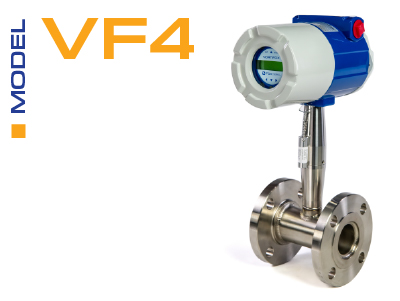
Vortex Series
The Fox Thermal Model VF4 vortex shedding flow meter is the newest product offered from Fox Thermal.
Key Features:
The Power over Ethernet (PoE) option for the Vortex series of flow meters delivers both data and electrical power over a single Ethernet cable. This feature offers:
Lower the overall infrastructur and installations costs with this advanced feature.
Try the Configurator/Sizing App
Click on the "Configure a VF4" button to get started.
More Info
| - - | 0.5-inch | 0.75-inch | 1-inch | 1.5-inch | 2-inch | 3-inch | 4-inch | 6-inch | 8-inch | 10-inch | 12-inch |
|---|---|---|---|---|---|---|---|---|---|---|---|
| gpm | 0.9 22 |
1.4 40 |
2.2 67 |
5.5 166 |
9.2 276 |
21 618 |
36 1076 |
81 2437 |
142 4270 |
224 6715 |
317 9501 |
| - - | 15 mm | 20 mm | 25 mm | 40 mm | 50 mm | 80 mm | 100 mm | 150 mm | 200 mm | 250 mm | 300 mm |
|---|---|---|---|---|---|---|---|---|---|---|---|
| m³/hr | 0.2 5 |
0.3 9 |
0.5 15 |
1.3 38 |
2.1 63 |
4.7 140 |
8.1 244 |
18 554 |
32 970 |
51 1525 |
72 2158 |
| 0.5-inch | 0.75-inch | 1-inch | 1.5-inch | 2-inch | 3-inch | 4-inch | 6-inch | 8-inch | 10-inch | 12-inch | |
|---|---|---|---|---|---|---|---|---|---|---|---|
| ft/sec | 175 | 250 | 250 | 300 | 300 | 300 | 300 | 300 | 300 | 300 | 300 |
| 15 mm | 20 mm | 25 mm | 40 mm | 50 mm | 80 mm | 100 mm | 150 mm | 200 mm | 250 mm | 300 mm | |
|---|---|---|---|---|---|---|---|---|---|---|---|
| m/sec | 53 | 76 | 76 | 90 | 90 | 90 | 90 | 90 | 90 | 90 | 90 |
| Process Connection | Material | Rating |
|---|---|---|
| Flanged | 316L SS, A105 carbon steel, C276 Hastalloy | 150, 300, 600, 900 lb |
| Wafer | 316L SS, A105 carbon steel, C276 Hastalloy | 600 lb |
| Full Scale Operating Pressure | Maximum Over-Range Pressure | ||
|---|---|---|---|
| psia | bara | psia | bara |
| 30 | 2 | 60 | 4 |
| 100 | 7 | 200 | 14 |
| 300 | 20 | 600 | 40 |
| 500 | 35 | 1000 | 70 |
| 1500 | 100 | 2750 | 175 |
CE: Approved
FM and FMc: Approved
ATEX: Approved
IECEx: Approved
Talk with our application specialist or a rep near you for sizing and materials requirements. See Model Codes document for more details on options.
The Fox Thermal Model VF4 is the newest vortex shedding flow meter offered from Fox Thermal.
For complete specs please see the Fox Thermal Model VF4 Flow Meter Datasheet.
Copyright © 2025
Fox Thermal | 399 Reservation Rd. | Marina, CA 93933 | (831) 384-4300 | www.foxthermal.com
This website stores cookies on your computer. These cookie are used to collect information about how you interact with our website and allow us to remember you. We use this information in order to improve and customize your browsing experience and for analytics and metrics about our visitors both on this website and other media. To find out more about the cookies we use, see our Cookie Policy and our Privacy Policy.
We won't track your information when you visit our site. But in order to comply with your preferences, we'll have to use just one tiny cookie so that you're not asked to make this choice again.
This site uses cookies. We use cookies mainly to improve and analyze your experience on our websites and for marketing purposes. Because we respect your right to privacy, you can choose not to allow some types of cookies. Click on the different category headings to find out more and change your default settings. Blocking some types of cookies may negatively impact your experience on the site and limit the services we are able to provide.
Necessary cookies enable core functionality such as security, network management, and accessibility. You may disable these by changing your browser settings, but this may affect how the website functions.
Analytics cookies help us improve our website by collecting and reporting information on its usage.
We use cookies to make our ads more engaging and valuable to site visitors. Some common applications of cookies are to select advertising based on what’s relevant to a user; to improve reporting on ad campaign performance; and to avoid showing ads the user has already seen.
We use a set of cookies that are optional for the website to function. They are usually only set in response to information provided to the website to personalize and optimize your experience as well as remember your chat history.
Subscribe to Fox eNewsletter
Stay up to date with the latest news, product updates, and industry insights from Fox Thermal.
Sign up below to receive our newsletter directly in your inbox.
We respect your privacy. Unsubscribe at any time.
Contact Fox Thermal
Fill out the form below to contact a Fox Thermal Representative.
Need to talk to someone immediately, give us a call, 831-384-4300.