Contact Sales Fox Thermal
Fill out the form below to contact a Fox Thermal Representative.
Need to talk to someone immediately, give us a call, 831-384-4300.
Account Logout
Are you sure you want to log out?
Contact Sales Fox Thermal
Fill out the form below to contact a Fox Thermal Representative.
Need to talk to someone immediately, give us a call, 831-384-4300.
Are you sure you want to log out?
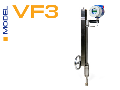
Vortex Series
The Fox Thermal Model VF3 vortex shedding flow meter is the newest product offered from Fox Thermal.
Key Features:
The Power over Ethernet (PoE) option for the series of flow meters delivers both data and electrical power over a single Ethernet cable. This feature offers:
Lower the overall infrastructur and installations costs with this advanced feature.
Try the Configurator/Sizing App
Click on the "Configure a VF3" button to get started.
More Info
| - - | 3-inch | 6-inch | 8-inch | 12-inch | 16-inch | 24-inch |
|---|---|---|---|---|---|---|
| gpm | 21 618 |
81 2437 |
142 4270 |
317 9501 |
501 15043 |
1138 34144 |
| - - | 80 mm | 150 mm | 200 mm | 300 mm | 400 mm | 600 mm |
|---|---|---|---|---|---|---|
| m³/hr | 5.2 157 |
20.4 614 |
35.4 1062 |
79.2 2337 |
125 3753 |
284 8537 |
| Pressure | 3-inch | 6-inch | 8-inch | 12-inch | 16-inch | 24-inch |
|---|---|---|---|---|---|---|
| 5 psig | 205 2721 |
800 10633 |
1385 18412 |
3099 41196 |
4893 65039 |
11132 147954 |
| 100 psig | 486 14246 |
1831 55674 |
3170 96407 |
7092 215703 |
11197 340546 |
25472 774698 |
| 200 psig | 632 25948 |
2471 101405 |
4278 175595 |
9572 392880 |
15111 620268 |
34377 1411029 |
| 300 psig | 762 37652 |
2976 147145 |
5153 254799 |
11530 570093 |
18203 900047 |
41410 2047489 |
| 400 psig | 873 49494 |
3412 193420 |
5908 334930 |
13219 749382 |
20870 1183103 |
47477 2691404 |
| 500 psig | 974 61543 |
3805 240507 |
6588 416468 |
14741 931816 |
23272 1471125 |
52942 3346615 |
| Pressure | 80 mm | 150 mm | 200 mm | 300 mm | 400 mm | 600 mm |
|---|---|---|---|---|---|---|
| 0 barg | 81 938 |
316 3667 |
548 6350 |
1226 14209 |
1936 22432 |
4404 51039 |
| 5 barg | 187 4986 |
729 19486 |
1263 33742 |
2826 75495 |
4461 119189 |
10151 271187 |
| 10 barg | 249 8859 |
972 34620 |
1683 59949 |
3767 134132 |
5947 211764 |
13530 481821 |
| 15 barg | 298 12700 |
1164 49629 |
2016 85939 |
4510 192283 |
7120 303570 |
16200 690705 |
| 20 barg | 340 16550 |
1329 64676 |
2301 111995 |
5148 250581 |
8128 395609 |
18493 900119 |
| 30 barg | 413 24357 |
1612 95187 |
2791 164827 |
6246 368789 |
9860 582234 |
22435 1324739 |
| Pressure | 3-inch | 6-inch | 8-inch | 12-inch | 16-inch | 24-inch |
|---|---|---|---|---|---|---|
| 0 psig | 56 924 |
220 3611 |
381 6253 |
852 13991 |
1345 22089 |
3059 50250 |
| 100 psig | 157 7236 |
615 28379 |
1065 48696 |
2383 109564 |
3763 172977 |
8560 393500 |
| 200 psig | 216 13588 |
843 53101 |
1460 91950 |
3266 205732 |
5156 324804 |
11729 738886 |
| 300 psig | 262 19974 |
1022 78059 |
1770 135169 |
3960 302430 |
6251 477467 |
14221 1086176 |
| 400 psig | 301 26391 |
1175 103136 |
2034 178593 |
4551 399588 |
7186 630859 |
16346 1435121 |
| 500 psig | 335 32834 |
1310 128314 |
2269 222191 |
5077 497136 |
8015 784865 |
18233 1785464 |
| Pressure | 80 mm | 150 mm | 200 mm | 300 mm | 400 mm | 600 mm |
|---|---|---|---|---|---|---|
| 0 barg | 89 1463 |
347 5716 |
601 9897 |
1345 22145 |
2124 34962 |
4833 79547 |
| 5 barg | 217 8702 |
847 34006 |
1467 58885 |
3282 131751 |
5181 208004 |
11788 473266 |
| 10 barg | 294 15975 |
1148 62430 |
1987 108105 |
4446 241878 |
7020 381870 |
15972 868857 |
| 15 barg | 355 23280 |
1385 90979 |
2399 157542 |
5368 352487 |
8474 556497 |
19282 1266182 |
| 20 barg | 407 30615 |
1589 119642 |
2751 207175 |
6156 463539 |
9718 731823 |
22112 1665095 |
| 30 barg | 495 45361 |
1934 177268 |
3349 306961 |
7493 686801 |
11829 1084302 |
26915 2467081 |
| Probe Seal | Process Connection | Material | Rating |
|---|---|---|---|
| Compression Fitting | 2-inch male NPT | 316L SS | ANSI 600 lb |
| Compression Fitting | 2-inch 150 lb flange | 316L SS | ANSI 150 lb |
| Compression Fitting | 2-inch 300 lb flange | 316L SS | ANSI 300 lb |
| Compression Fitting | 2-inch 600 lb flange | 316L SS | ANSI 600 lb |
| Compression Fitting | 2-inch 900 lb flange | 316L SS | ANSI 900 lb |
| Packing Gland | 2-inch male NPT | 316L SS | 50 psig |
| Packing Gland | 2-inch 150 lb flange | 316L SS | 50 psig |
| Packing Gland | 2-inch 300 lb flange | 316L SS | 50 psig |
| Packing Gland & Removable Retractor | 2-inch male NPT | 316L SS | ANSI 300 lb |
| Packing Gland & Removable Retractor | 2-inch 150 lb flange | 316L SS | ANSI 300 lb |
| Packing Gland & Removable Retractor | 2-inch 300 lb flange | 316L SS | ANSI 300 lb |
| Packing Gland & Permanent Retractor | 2-inch male NPT | 316L SS | ANSI 600 lb |
| Packing Gland & Permanent Retractor | 2-inch 150 lb flange | 316L SS | ANSI 150 lb |
| Packing Gland & Permanent Retractor | 2-inch 300 lb flange | 316L SS | ANSI 300 lb |
| Packing Gland & Permanent Retractor | 2-inch 600 lb flange | 316L SS | ANSI 600 lb |
CE: Approved
FM and FMc: Approved
ATEX: Approved
IECEx: Approved
Talk with our application specialist or a rep near you for sizing and materials requirements. See Model Codes document for more details on options.
The Fox Thermal Model VF3 is the newest vortex shedding flow meter offered from Fox Thermal.
For complete specs please see the Fox Thermal Model VF3 Flow Meter Datasheet.
Copyright © 2025
Fox Thermal | 399 Reservation Rd. | Marina, CA 93933 | (831) 384-4300 | www.foxthermal.com
This website stores cookies on your computer. These cookie are used to collect information about how you interact with our website and allow us to remember you. We use this information in order to improve and customize your browsing experience and for analytics and metrics about our visitors both on this website and other media. To find out more about the cookies we use, see our Cookie Policy and our Privacy Policy.
We won't track your information when you visit our site. But in order to comply with your preferences, we'll have to use just one tiny cookie so that you're not asked to make this choice again.
This site uses cookies. We use cookies mainly to improve and analyze your experience on our websites and for marketing purposes. Because we respect your right to privacy, you can choose not to allow some types of cookies. Click on the different category headings to find out more and change your default settings. Blocking some types of cookies may negatively impact your experience on the site and limit the services we are able to provide.
Necessary cookies enable core functionality such as security, network management, and accessibility. You may disable these by changing your browser settings, but this may affect how the website functions.
Analytics cookies help us improve our website by collecting and reporting information on its usage.
We use cookies to make our ads more engaging and valuable to site visitors. Some common applications of cookies are to select advertising based on what’s relevant to a user; to improve reporting on ad campaign performance; and to avoid showing ads the user has already seen.
We use a set of cookies that are optional for the website to function. They are usually only set in response to information provided to the website to personalize and optimize your experience as well as remember your chat history.
Subscribe to Fox eNewsletter
Stay up to date with the latest news, product updates, and industry insights from Fox Thermal.
Sign up below to receive our newsletter directly in your inbox.
We respect your privacy. Unsubscribe at any time.
Contact Fox Thermal
Fill out the form below to contact a Fox Thermal Representative.
Need to talk to someone immediately, give us a call, 831-384-4300.